If you choose to build your own Root or Mote you can download the .stl files below. Each case requires 2 screws, we used socket cap screws with 3.8mm diameter 2mm depth heads with a thread diameter of 2mm and a thread length of at least 6mm. A longer thread is OK as there is space behind the screw boss. The mote case also has spaces on the bottom for stick on rubber feet, we used 6mm diameter dome shaped self adhesive pads.
Root case for Raspberry Pi. Designed for Pi3 but fits Pi2 as well.

Mote case.

Getting started:
Some steps are for Mote Only as marked. Root is integral to Mote so many parts are the same. If you have Root only then some steps are more complicated due to the lack of a direct interface to the Root web server. To see this interface a network connection is required or you can connect a screen to the HDMI port on the Root.
- Install AutoMaker updates on the computer you will be using to control Robox. Minimum requirement to discover Root or Mote is AutoMaker Version 3.01.01.
www.cel-robox.com/downloads/ - Plug your Robox in and connect your computer to it directly via USB as you normally would. Allow any firmware updates to complete as requested. Do not power off until firmware is updated and the machine is displayed in AutoMaker and ready to use again. If you cannot connect to Robox or there are any errors please report these via the support portal www.cel-robox.com/support/
- Once the software and firmware are updated and ready you can power off and disconnect your Robox. Keep the computer on with AutoMaker running.
- Unpack all the parts, check everything is present and report immediately if something is missing.
- Gently press the microSD card to ensure it is still seated in the rear of the case following shipping.
- Mote Only Assemble the Desktop stand onto the rear of the Mote case. The cables can pass through the loop on the stand to keep them tidy.
- Connect a LAN cable to the router which serves the same network as your computer. Connect the other end of this cable to the LAN port on Mote or Root.
- Root only If you are using a HDMI screen to view the IP address of Root then you must connect the HDMI before the power to ensure the Pi starts the HDMI devices.
- Connect a Robox to the Mote or Root via the USB cable. Turn the Robox power on.
- Fit the appropriate mains connection to the power supply or provide a micro USB power supply with 5 Volts @ 2.5 Amps. Connect this to the Micro USB Power connector on the side of Mote or Root and turn the power on.
- When power is provided the Pi will boot and load Root software automatically, this takes around 30 seconds. Mote Only If the screen remains blank please check the HDMI connector is pressed in and power is connected correctly and able to provide correct voltage and amps. Contact support if you can’t get the screen to work. You may still be able to use the Root services without the screen so continue to follow the steps below.
- In AutoMaker go to the upper right cog icon (Preferences) and click it.
- In the Preferences menu click “Network”
- AutoMaker will automatically find Root instances on the same network.
Note: If your router does not allow the Root to be discovered you will need to find the IP address via the router admin page. Typically this is “Connected devices” or “IP list”. If you have the IP you can add it manually using the input below the list window. - In the screenshot below there are currently 3 active Root devices. You will only see one unless you have more Root devices on the network. It will automatically refresh every few seconds so give it 15 seconds or so to boot and assign an IP address before checking connections.

- The display will initially show the default settings of Root. Columns are Name, IP address, Version, Connection Icon (2 plugs) and finally a PIN entry box and a Connect button.
Note: Typically a home network is closed to outside connections by default. A user could change these settings in the Router administration pages if they wanted to view or allow access local devices from outside the local network. CEL will not provide advice on removing or altering network security and does not recommend this is done by anyone who cannot reduce the risks of doing so. The PIN is not intended as a security feature, only as a device to prevent accidental operation. Network security is not provided or implied. - Enter the default PIN 1111 and press Connect.
- If connection is successful the Connection Icon will change from 2 plugs to a single connected plug and the 2 buttons will replace the connect button, “Disconnect” which has obvious usage and “Launch Root Manager”, described below.
- At this stage your Robox is connected via USB to Root and Root is connected via the LAN cable and your network to AutoMaker. If you press the back key you will be able to control your Robox via the regular interface, you can skip to the final step.
If you have multiple Robox units you can connect these to Root and select them in the top left corner of AutoMaker as normal, there is a small change to Robox icons connected via Root. You can mix direct USB connections and Root connections with the same instance of AutoMaker and see the difference in the icons. Choosing a different colour for each Robox helps with control. Just double click the Robox icon in the top left corner and enter any name you want, pick a colour and press OK.
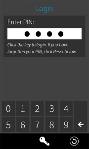
- Login Screen
The reset button will allow you to set the pin to the default “1111” by entering the details requested. Enter your pin and press the Key icon - Home Page / Status Page.
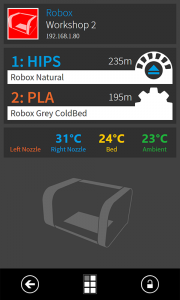
When you view the IP of your Root via a Mote, Smartphone or web browser you will see the status page or if you have several Robox units connected you will see the home page and you will see the arrow in the bottom left to return to the home page. Any Robox connected to this Root and powered on will be visible on the home page. - Status Page.
On the Home page of the Root Manager, click on the entry for your Robox. If you have named your Robox or changed the colour then the Name and Colour will appear as set. Different colours are useful when you have several Robox units, up to 6 Robox can be accommodated within the software. As there are only 4 USB ports on the Pi3 to connect more than 4 devices will require the addition of a USB hub.
The status page will vary depending on the status of your Robox. If a print is active then you will be able to Pause/Resume or Cancel. You can click on the icon of the Robox in the top left to change the colour and name of that Robox.
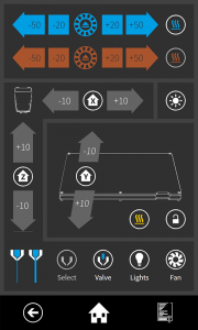
At the bottom centre of the screen the control icon gives access to the controls page.These pages have various tools which control similar functions to AutoMaker. - Control Page.
This page gives you control over various motions within the active printer. The upper section is material control. Blue and Orange sets of buttons. The blue buttons, Material 1: move the material toward + or away from – the head in various increments.
The heater button on the right will read the nozzle temperature setting from the associated SmartReel or material profile.
The bed heater icon will read the setting from a SmartReel and heat the bed to this temperature.
Axis movement and homing buttons are available.
Nozzle switching and valve controls will be available when present on the installed head along with light and fan controls.
Timelapse
Root Time Lapse Facility
AutoMaker V4.02.00 in combination with Root introduces a new facility to take time lapse images of a print as it progresses.
The facility requires a Robox Pro, or a Robox connected to a Root, AutoMaker running on a personal computer, a USB camera such as a Logitech C920 connected to the Root or Robox Pro, and a USB memory stick connected to the Root or Robox Pro. When enabled on a print, an image is when each layer is completed, and stored on the connected memory stick. There are many applications, such as Time Lapse Creator that can convert these images to a video, which show the printed object growing out of the bed.
In AutoMaker, the Network page shows which connected Roots have connected cameras.

If a Root has detected that a camera is connected, then the symbol in the camera column will be . If no camera is detected, or the Root is not connected, it will be
.
If the currently selected printer is associated with a Root with a connected camera, a snapshot panel with two combo boxes and an image captured from the camera will be displayed on the printer status page.

The left combo box selects a “camera profile”. The right combo box selects a camera. The image is updated every second or so.
Camera Profiles
A camera profile specifies a collection of settings for a camera. They can be inspected, created and edited in the Camera Profile page in the Library. Click the library button 

Profiles supplied with AutoMaker cannot be changed, but copies are easily created and can be edited. Click “New” at the bottom of the screen. Type a unique name into the combo box at the top and press the tab key to complete the name. All the fields should now become editable. Click “Save” at the bottom to save the profile.
The settings are grouped in sections and are described below.
Timelapse Section
| Setting | Default | Description |
| Headlight Off | Enabled | Turns off the headlight before capturing an image, then turns it back on |
| Ambient Light Off | Disabled | Turns off the ambient light before capturing an image, then turns it back on. |
| Move Before Capture | Enabled | Move the head to a specified position in X and Y before capturing an image. (Z will increase as the print progresses.) |
| Move To X | 50 | X position to which the head is moved. |
| Move To Y | 50 | Y position to which the head is moved. |
General Section
| Setting | Default | Description |
| Camera Name | (Any Camera) | Specifies the name of the camera for which this profile is intended. If set to (Any Camera), then it can be used with any camera. Otherwise, if selected, only cameras with the specified name will be available for selection in the Camera combo box. |
| Capture Width | 1080 | The width of the captured image in pixels. |
| Capture Height | 720 | The height of the captured image in pixels. |
Controls
Root uses a camera utility called “fswebcam” to capture images. This has a number of controls and settings. Exactly which controls are available, and the effect they have depends on the type of camera connected. The Control section is provided so that any required settings for a camera can be passed to the fswebcam facility.
In our experience, we have found that many USB cameras do not work well on the Raspberry Pi. One that does work well is the Logitech C920.
There are two types of control settings: command line settings for fswebcam are prefixed by “—“ and are passed to fswebcam as command line arguments. Control settings have no prefix and are passed to fswebcam as “—set setting=value”. For full details of all the available settings, please see the fswebcam documentation here: http://manpages.ubuntu.com/manpages/bionic/man1/fswebcam.1.html
Command line settings should be used with care as some settings may cause fswebcam to hang, return multiple images or none at all. Note that banners are always disabled. A couple of useful settings are described below.
| Setting | Default | Description |
| –skip | 0 | Specifies the number of frames to skip before capturing an image. Useful if, for example the camera automatically adjusts it exposure settings |
| –delay | 0 | Number of seconds to delay before capturing an image. Useful if the camera requires a little time to settle before a reliable image is captured. |
Below is a list of some available control settings. Exactly what these settings do depends on the connected camera and, is sadly often not documented. Experimentation to get the best results is probably the best approach.
| Control Name | Values |
| brightness | min=30 max=255 step=1 default=-8193 value=116 |
| contrast | min=0 max=10 step=1 default=57343 value=5 |
| saturation | min=0 max=200 step=1 default=57343 value=103 |
| white_balance_temperature_auto | default=1 value=1 |
| power_line_frequency | min=0 max=2 default=2 value=2 |
| white_balance_temperature | min=2500 max=10000 step=1 default=57343 value=4500 flags=inactive |
| sharpness | min=0 max=50 step=1 default=57343 value=25 |
| backlight_compensation | min=0 max=10 step=1 default=57343 value=0 |
| exposure_auto | min=0 max=3 default=0 value=3 |
| exposure_absolute | min=1 max=10000 step=1 default=156 value=156 flags=inactive |
| pan_absolute | min=-529200 max=529200 step=3600 default=0 value=0 |
| tilt_absolute | min=-432000 max=432000 step=3600 default=0 value=0 |
| focus_absolute | min=0 max=40 step=1 default=57343 value=0 |
| focus_auto | default=1 value=0 |
| zoom_absolute | min=0 max=317 step=1 default=57343 value=0 |
Making Time Lapse Images of a Print
If the currently selected printer is associated with a Root with a connected camera, a time lapse panel with a checkbox, two combo boxes and an image captured from the camera will be displayed on the settings page:

To capture time lapse images of a print, check the “Enable Time Lapse” checkbox. Select a camera profile in the top combo box, and a camera in the bottom one. Only profiles for which there is a suitable camera connected to the currently selected printer will be available in the combo box. Only cameras that are compatible with the selected camera profile will be available in the camera combo box. The image from the selected camera is updated every second or so. Click on the “Make” button at the bottom right of the page to start the print.
As the print progresses, time lapse images will be captured when each layer is completed. If a USB memory stick is connected to the Root, the images will be stored in a folder /$PRINTER_NAME/$JOB_ID where $PRINTER_NAME is the name assigned to the printer, and $JOB_ID is a unique id generated for the print job. If a usb memory stick is not connected, the images will be stored on the Root itself in “/home/pi/CEL Root/time lapse/$PRINTER_NAME/$JOB_ID”. These will have to be retrieved from the pi using a file transfer tool such as FileZilla. To log onto Root, use the username “pi” and password “CELRoot”. Remember to regularly delete the contents of the time lapse directory to avoid running out of storage.
Disabling The Time Lapse Facility
The snapshot panel can be disabled by clearing the “Show Snapshot Panel” option in the “Preferences Advanced”. The timelapse panel will still be available on the print settings page.

The timelapse facility can be completely disabled by clearing the “Search for Remote Cameras” option in the Preferences Environment panel:

It might make sense to do this if none of the connected Roots have a camera.
You could use putty or a similar program to access the pi hardware using the following details:
Username: pi
Password: CELRoot
More help?
Raspberry Pi is very widely used in a huge range of applications, Root runs Raspian which boots and then loads Root web server in a web browser, on Mote this is visible on the screen or can be viewed on any screen connected to the HDMI output of the Pi or a web browser directed to the IP of the Root as determined by the Router it is connected to. You can plug a mouse and keyboard into Root, if you want to stop it from booting to Root or to access Raspian then you will need a keyboard or SSH access.
CTRL+ALT+t will open a new terminal window
Use commands such as the following, there are many more options:
sudo shutdown
sudo reboot
CTRL+ALT+F1 will open the console giving access to the Pi OS.
If you have purchased a Root or Mote from us you can use our support portal for additional help. www.cel-robox.com/support/
If you want to chat about this or see something missing or incorrect on this page please notify us via the forum.


